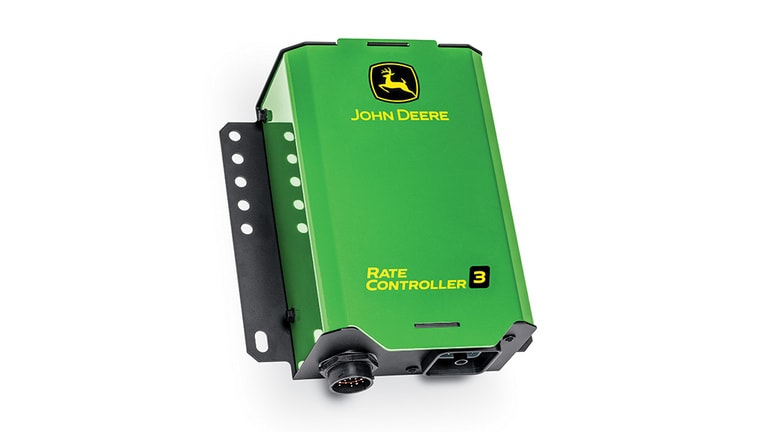
<div class="accordion-wrap"><div class="accordion2_component"><div class="accordion2_top"><div class="text-size-medium text-weight-bold">Rate Controller 3 advantage</div><div class="accordion2_icon w-embed"><svg width="100%" height="100%" viewBox="0 0 32 32" fill="none" xmlns="http://www.w3.org/2000/svg"><path d="M25.3333 15.667V16.3336C25.3333 16.7018 25.0349 17.0003 24.6667 17.0003H17V24.667C17 25.0351 16.7015 25.3336 16.3333 25.3336H15.6667C15.2985 25.3336 15 25.0351 15 24.667V17.0003H7.3333C6.96511 17.0003 6.66663 16.7018 6.66663 16.3336V15.667C6.66663 15.2988 6.96511 15.0003 7.3333 15.0003H15V7.33365C15 6.96546 15.2985 6.66699 15.6667 6.66699H16.3333C16.7015 6.66699 17 6.96546 17 7.33365V15.0003H24.6667C25.0349 15.0003 25.3333 15.2988 25.3333 15.667Z" fill="currentColor"></path></svg></div></div><div style="width: 1118px; height: 0px;" class="accordion2_bottom"><div class="margin-bottom margin-small"><div><div class="seccion-images"></div> <p>The John Deere Rate Controller 3 automates rate control to reduce input costs, minimize over and under application, and boost land stewardship.</p> <div class="seccion-images"> <div> <img src="https://salesmanual.deere.com/customer/sales/salesmanual/images/NA/ams/rate_controller/r4k091310_rate_ctrl_3_advantage.jpg" alt="John Deere Rate Controller 3"><span class="caption">John Deere Rate Controller 3</span> </div> </div> <p>The Rate Controller 3 is compatible with John Deere Gen 4 V2, G5, and G5<sup>Plus</sup> Displays. It stands out amongst the rest through never-before-seen integration <span data-teams="true">with the display</span>, more product capacity, and easy installation and serviceability.</p> <p> </p> <p>This rate controller remains versatile and reliable for countless operational needs. Compatibility includes liquid and anhydrous applications via planters, anhydrous ammonia (NH3) applicators, self-propelled sprayers, liquid fertilizer applicators, pull-type sprayers, ProGator GPS sprayers, and more.</p></div></div></div></div><div class="accordion2_component"><div class="accordion2_top"><div class="text-size-medium text-weight-bold">More product capacity</div><div class="accordion2_icon w-embed"><svg width="100%" height="100%" viewBox="0 0 32 32" fill="none" xmlns="http://www.w3.org/2000/svg"><path d="M25.3333 15.667V16.3336C25.3333 16.7018 25.0349 17.0003 24.6667 17.0003H17V24.667C17 25.0351 16.7015 25.3336 16.3333 25.3336H15.6667C15.2985 25.3336 15 25.0351 15 24.667V17.0003H7.3333C6.96511 17.0003 6.66663 16.7018 6.66663 16.3336V15.667C6.66663 15.2988 6.96511 15.0003 7.3333 15.0003H15V7.33365C15 6.96546 15.2985 6.66699 15.6667 6.66699H16.3333C16.7015 6.66699 17 6.96546 17 7.33365V15.0003H24.6667C25.0349 15.0003 25.3333 15.2988 25.3333 15.667Z" fill="currentColor"></path></svg></div></div><div style="width: 1118px; height: 0px;" class="accordion2_bottom"><div class="margin-bottom margin-small"><div><div class="seccion-images"></div> <p>With the John Deere Rate Controller 3, operators gain additional product capacity when compared to the GreenStar™ Rate Controller. The Rate Controller 3 can control up to 2 products – liquid and/or anhydrous in any combination:</p> <ul> <li>1 liquid product</li> <li>2 liquid products</li> <li>Anhydrous and 1 liquid product</li> <li>Anhydrous</li> </ul> <p>The increased product capacity of the Rate Controller 3 enables one controller, to complete the same work that would have required two GreenStar™ Rate Controllers in the past. This allows such tasks to be completed simultaneously during a single field pass through one installation and one setup. This minimizes the amount of time and effort required to prepare for work.</p> <p> </p> <p>The controller can run up to 16 sections. Things that impact section count include:</p> <ul> <li>adding an additional product. The 16 sections must them be divided between products.</li> <li>adding an accessory valve. Section capability would be reduced by one section for each accessory valve utilizing a section drive. Examples include left fence row, right fence row, agitation, or recirculation.</li> </ul> <p><em>NOTE: Two types of direct injection are supported – Raven Sidekick Pro ISO and direct control assigned as the second liquid operation. Using the Raven Sidekick Pro ISO for direct injection will not impact the product or section capacity of the Rate Controller 3. The user can add up to 3 direct injection pumps linked to a single operation, setting up and controlling through ISOBUS VT.</em></p> <p> </p> <p>During setup, an unlimited number of profiles can be created, saved, and shared with other displays via USB. Additionally, the Rate Controller 3 will remember the last profile used, making it easy for an operator to get started if swapping machines is required. The ability to create unlimited profiles saves the operator time in the cab and increases the accuracy of setup, making it easy to switch between operations and machines throughout the growing season.</p> <div class="seccion-images"> <div> <img src="https://salesmanual.deere.com/customer/sales/salesmanual/images/NA/ams/rate_controller/add_profile_391x450.jpg" alt="Add profile"><span class="caption">Add profile</span> </div> </div></div></div></div></div><div class="accordion2_component"><div class="accordion2_top"><div class="text-size-medium text-weight-bold">Overall integrated experience</div><div class="accordion2_icon w-embed"><svg width="100%" height="100%" viewBox="0 0 32 32" fill="none" xmlns="http://www.w3.org/2000/svg"><path d="M25.3333 15.667V16.3336C25.3333 16.7018 25.0349 17.0003 24.6667 17.0003H17V24.667C17 25.0351 16.7015 25.3336 16.3333 25.3336H15.6667C15.2985 25.3336 15 25.0351 15 24.667V17.0003H7.3333C6.96511 17.0003 6.66663 16.7018 6.66663 16.3336V15.667C6.66663 15.2988 6.96511 15.0003 7.3333 15.0003H15V7.33365C15 6.96546 15.2985 6.66699 15.6667 6.66699H16.3333C16.7015 6.66699 17 6.96546 17 7.33365V15.0003H24.6667C25.0349 15.0003 25.3333 15.2988 25.3333 15.667Z" fill="currentColor"></path></svg></div></div><div style="width: 1118px; height: 0px;" class="accordion2_bottom"><div class="margin-bottom margin-small"><div><div class="seccion-images"></div> <p>Rate control is a core technology offering that drives customers to purchase other John Deere technology. This increases the importance of a top-notch rate control experience!</p> <h5>New Rate Control App</h5> <div class="seccion-images"> <div> <img src="https://salesmanual.deere.com/customer/sales/salesmanual/images/NA/ams/rate_controller/rate_control_app_183s.jpg" alt="Rate control app located in the display menu"><span class="caption">Rate control app located in the display menu</span> </div> </div> <p>The John Deere Rate Controller 3 brings about a next generation experience for the operator. When a Rate Controller 3 is installed on a machine or implement, it looks and feels like other integrated John Deere technology products. Rate control is no longer setup and managed through the ISOBUS VT app but instead the controller is setup, monitored, and adjusted through an all new rate control app in the display menu. All profile creation, rate control setup, and calibrations/diagnostics are located with this app.</p> <div class="seccion-images"> <div> <img src="https://salesmanual.deere.com/customer/sales/salesmanual/images/NA/ams/rate_controller/new_rate_controller_app_576x219.jpg" alt="New Rate Controller app compared to the previous ISOBUT VT screen"><span class="caption">New Rate Controller app compared to the previous ISOBUT VT screen</span> </div> </div> <p>Within Controller Setup, all profile settings can be established and assigned to the desired Rate Controller 3.</p> <p> </p> <p><em>NOTE: The Master Switch can be set up to use virtual on/off, a switch box, or a foot switch. A foot switch is not required.</em></p> <div class="seccion-images"> <div> <img src="https://salesmanual.deere.com/customer/sales/salesmanual/images/NA/ams/rate_controller/rate_controller_setup_450x342.jpg" alt="Rate Controller setup"><span class="caption">Rate Controller setup</span> </div> </div> <p>Within Calibrations and Diagnostics, the operator can complete necessary calibrations of the flowmeter, pressure sensor, control valve, etc. along with viewing controller and diagnostic information.</p> <div class="seccion-images"> <div> <img src="https://salesmanual.deere.com/customer/sales/salesmanual/images/NA/ams/rate_controller/calibrations_diagnostics_774x184.jpg" alt="Calibrations and Diagnostics"><span class="caption">Calibrations and Diagnostics</span> </div> </div> <p>A summary page then offers an overall view of the settings to quickly verify accurate setup. This is especially beneficial when utilizing Remote Display Access for one consolidated view of the current setup with the ability to easily make adjustments through the Controller Setup shortcut.</p> <div class="seccion-images"> <div> <img src="https://salesmanual.deere.com/customer/sales/salesmanual/images/NA/ams/rate_controller/setup_summary_423x316.jpg" alt="Setup summary"><span class="caption">Setup summary</span> </div> </div> <h5>New Run Pages</h5> <div class="seccion-images"></div> <p>Create customized run pages using new run pages modules. This allows the operator to quickly and easily get to work with confidence while keeping a closer eye on every aspect of the operation. For instance, monitor both planting and application through one run page. This is the first time in John Deere history an operator can easily combine a planter and rate controller into one view. The impact of this is huge, especially if running two liquid applications along with planting.</p> <div class="seccion-images"> <div> <img src="https://salesmanual.deere.com/customer/sales/salesmanual/images/NA/ams/rate_controller/run_page_example_463x246.jpg" alt="Run Page Example: Planter and Two Liquid Applications"><span class="caption">Run Page Example: Planter and Two Liquid Applications</span> </div> </div></div></div></div></div><div class="accordion2_component"><div class="accordion2_top"><div class="text-size-medium text-weight-bold">Easy installation and serviceability</div><div class="accordion2_icon w-embed"><svg width="100%" height="100%" viewBox="0 0 32 32" fill="none" xmlns="http://www.w3.org/2000/svg"><path d="M25.3333 15.667V16.3336C25.3333 16.7018 25.0349 17.0003 24.6667 17.0003H17V24.667C17 25.0351 16.7015 25.3336 16.3333 25.3336H15.6667C15.2985 25.3336 15 25.0351 15 24.667V17.0003H7.3333C6.96511 17.0003 6.66663 16.7018 6.66663 16.3336V15.667C6.66663 15.2988 6.96511 15.0003 7.3333 15.0003H15V7.33365C15 6.96546 15.2985 6.66699 15.6667 6.66699H16.3333C16.7015 6.66699 17 6.96546 17 7.33365V15.0003H24.6667C25.0349 15.0003 25.3333 15.2988 25.3333 15.667Z" fill="currentColor"></path></svg></div></div><div style="width: 1118px; height: 0px;" class="accordion2_bottom"><div class="margin-bottom margin-small"><div><h5>New harnesses and adapters</h5> <div class="seccion-images"></div> <p>The John Deere Rate Controller 3 brings with it an entirely new offering of harnesses and adapters making installation and serviceability much easier. The new connection allows the user to easily connect and disconnect the parts from one another while offering a great seal which protects the internal wiring from weathering or other damage.</p> <div class="seccion-images"> <div> <img src="https://salesmanual.deere.com/customer/sales/salesmanual/images/NA/ams/rate_controller/r4i018493_main_rate_controller_harness_450x291.jpg" alt="Main rate controller harness"><span class="caption">Main rate controller harness</span> </div> </div> <p>Adapters are offered for customers who would like to utilize previous harnessing with the John Deere Rate Controller 3.</p> <h5>Connectors</h5> <div class="seccion-images"></div> <p>There are two connectors on the bottom of the Rate Controller 3 – the power harness connector and implement harness connector. Both of these connectors reinforce a strong seal that protects against weathering and other potential damage no matter the work environment - in the field, on the golf course, in the orchard, etc.</p> <div class="seccion-images"> <div> <img src="https://salesmanual.deere.com/customer/sales/salesmanual/images/NA/ams/rate_controller/r4k091307_rate_ctrl_3_connector.jpg" alt="Rate Controller 3 Connectors"><span class="caption">Rate Controller 3 Connectors</span> </div> </div> <p>1. The power harness connector is the 19-pin connector. This is the connector used to install the main rate controller harness which is the power harness included in base when purchasing the Rate Controller 3.</p> <p> </p> <p>The steps to install main rate controller harness:</p> <ul> <li>Line up the connectors</li> <li>Twist them together</li> </ul> <div class="seccion-images"> <div> <img src="https://salesmanual.deere.com/customer/sales/salesmanual/images/NA/ams/rate_controller/r4k091303_rc3_power_harness_connector.jpg" alt="Power Harness Connector attached to the Main Rate Controller Harness"><span class="caption">Power Harness Connector attached to the Main Rate Controller Harness</span> </div> </div> <p>2. The implement harness connector is the 48-pin connector. This new design adds flexibility and increases compatibility of harnessing for the controller. The person installing or servicing the controller, can more easily reconfigure pins to fit compatibility needs.</p> <p> </p> <p>The steps to install implement harnessing:</p> <ul> <li>Line up the connectors</li> <li>Tighten a bolt to secure in place</li> </ul> <div class="seccion-images"> <div> <img src="https://salesmanual.deere.com/customer/sales/salesmanual/images/NA/ams/rate_controller/r4k091302_rc3_implement_harness_connector.jpg" alt="Implement harness connector attached to an adapter"><span class="caption">Implement harness connector attached to an adapter</span> </div> </div> <h5>Diagnostic Light</h5> <div class="seccion-images"></div> <p>A diagnostic light is located on top of the Rate Controller 3 for visibility to the controller status or any diagnostic errors. This is a proactive view available prior to accessing further diagnostics in the display.</p> <p> </p> <p>The operator can diagnose through color and number of blinks.</p> <p> </p> <table style="border-collapse: collapse;" border="1" cellspacing="1" cellpadding="1"> <tbody> <tr> <td width="62"><p><strong>Color</strong></p></td> <td width="130"><p><strong>Number of Blinks</strong></p></td> <td width="410"><p><strong>Status</strong></p></td> </tr> <tr> <td width="62"><p>Off</p></td> <td width="130"><p>Solid</p></td> <td width="410"><p>No Power, Not Programmed, or Programming</p></td> </tr> <tr> <td width="62"><p>Red</p></td> <td width="130"><p>Four</p></td> <td width="410"><p>Powered & Programmed, No Healthy CAN Bus Connected</p></td> </tr> <tr> <td width="62"><p>Pink</p></td> <td width="130"><p>Three</p></td> <td width="410"><p>CAN Bus Connected; Address Claim Failed</p></td> </tr> <tr> <td width="62"><p>Yellow</p></td> <td width="130"><p>Two</p></td> <td width="410"><p>CAN Bus Connected & Address Claimed, Display Not Detected</p></td> </tr> <tr> <td width="62"><p>Blue</p></td> <td width="130"><p>One</p></td> <td width="410"><p>Display Detected; Compatible App Not Detected</p></td> </tr> <tr> <td width="62"><p>Green</p></td> <td width="130"><p>Solid</p></td> <td width="410"><p>Communication Established with App</p></td> </tr> </tbody> </table> <p>This key will be accessible in Equipment Mobile as well as in the Operator’s Manual and Technical Manual.</p></div></div></div></div><div class="accordion2_component"><div class="accordion2_top"><div class="text-size-medium text-weight-bold">Enable additional precision technology</div><div class="accordion2_icon w-embed"><svg width="100%" height="100%" viewBox="0 0 32 32" fill="none" xmlns="http://www.w3.org/2000/svg"><path d="M25.3333 15.667V16.3336C25.3333 16.7018 25.0349 17.0003 24.6667 17.0003H17V24.667C17 25.0351 16.7015 25.3336 16.3333 25.3336H15.6667C15.2985 25.3336 15 25.0351 15 24.667V17.0003H7.3333C6.96511 17.0003 6.66663 16.7018 6.66663 16.3336V15.667C6.66663 15.2988 6.96511 15.0003 7.3333 15.0003H15V7.33365C15 6.96546 15.2985 6.66699 15.6667 6.66699H16.3333C16.7015 6.66699 17 6.96546 17 7.33365V15.0003H24.6667C25.0349 15.0003 25.3333 15.2988 25.3333 15.667Z" fill="currentColor"></path></svg></div></div><div style="width: 1118px; height: 0px;" class="accordion2_bottom"><div class="margin-bottom margin-small"><div><div class="seccion-images"></div> <p>Rate control is the essence of precision technology. It enables product to be applied at a specified rate, where and when it is needed most. Although, the ability and functionality available through the controller grows when paired with other John Deere technology like a StarFire™ Receiver and MTG/Modem with JDLink™ Connectivity.</p> <h5>Documentation</h5> <div class="seccion-images"></div> <p>Pair the John Deere Rate Controller 3 with a compatible display and receiver to enable mapping and reporting for practices that otherwise may not have data captured. That data will then be logged on the display and can be transferred to Operations Center. If using an MTG or modem with JDLink™ Connectivity, experience a seamless flow of data, along with near real-time monitoring and analysis. This expands visibility in-field and remotely to make on the fly decisions. For example, maybe an adjustment needs made to settings in order to optimize performance. This also provides accurate documentation of work completed in each field and the ability to make even more educated decisions in the future.</p> <div class="seccion-images"> <div> <img src="https://salesmanual.deere.com/customer/sales/salesmanual/images/NA/ams/rate_controller/target_rate_layer_700x219.jpg" alt="Target rate layer versus actual as-applied map"><span class="caption">Target rate layer versus actual as-applied map</span> </div> </div> <p>Having true documentation of what actual work occurred in each field is extremely beneficial. When that granularity is multiplied across all fields, it gives the operation a full record of work complete overtime and the ability to compare season to season and year to year.</p> <p> </p> <p><em>NOTE: New with the Rate Controller 3, if a pressure sensor is installed on a liquid profile, a pressure map layer will also be available.</em></p> <h5>Section Control</h5> <div class="seccion-images"></div> <p>Rate control is a foundational requirement to use Section Control. The John Deere Rate Controller 3 and Section Control work together with the receiver (global positioning system) to understand where product has already been applied, triggering section shut off and turn on, alleviating over or under application.</p> <p> </p> <p>With the correct setup in the cab, this functionality can also be extremely beneficial when crossing in and out of headlands or crossing an interior boundary. Section Control further:</p> <ul> <li>Reduces input costs caused by overlap</li> <li>Reduces weed pressure or nutrient deficiency caused by missed sections</li> <li>Reduces operator fatigue from manual turn on/shut off</li> <li>Increases overall yield</li> <li>Enhances land stewardship</li> </ul> <p><em>NOTE: A Section Control activation is required to use Section Control.</em></p> <p> </p> <p>For many customer segments, the impact of environmental considerations and food production practices are becoming more and more driven by consumers. Purchasing decisions are changing immensely with the desire to know where food and textiles originated and how they were produced. The ability to track and report farming practices is becoming important not just at an operational level but also to the overall market. This makes adopting or upgrading rate control more important than ever before.</p></div></div></div></div></div>